Sunday 10 May 2020

IVRS Based Home Automation with Immediate Voice & SMS Feedback Using Arduino TTS - GSM SIM800L DTMF


Watch Video Demonstration Carefully Till End -- IVRS Based Home Automation with Immediate Voice & SMS Feedback Using Arduino TTS - GSM SIM800L DTMF

PLEASE SUBSCRIBE FOR MORE PROJECT VIDEOS --► HTTP://BIT.LY/29VPRS9

Project Abstract and Block Diagram   Link► http://svsembedded.com/IVRS_Based_Home_Automation_With_Immediate_Voice_SMS_Feedback.php
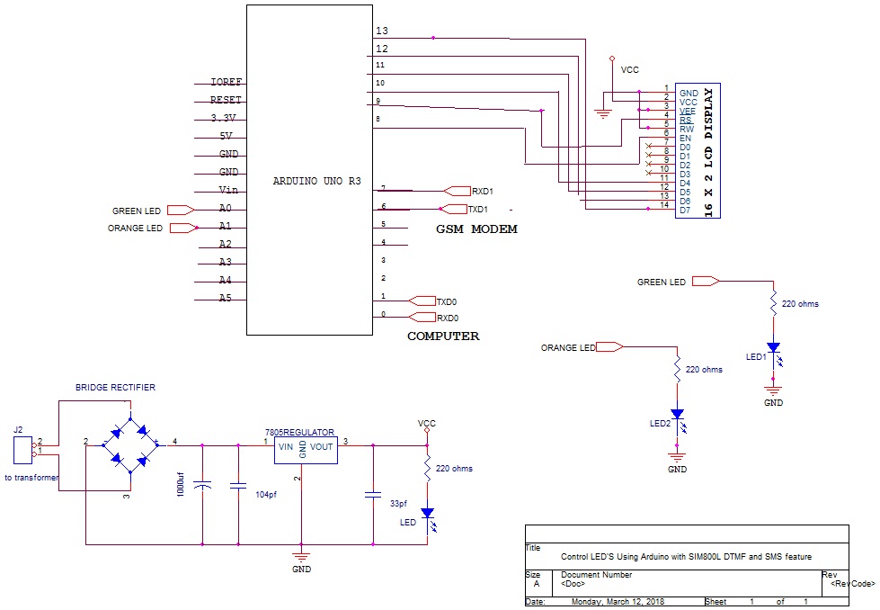
SCHEMATIC DIAGRAM:

FINAL SOFTWARE CODE:

#include<LiquidCrystal.h>
LiquidCrystal lcd(8, 9, 10, 11, 12, 13);/////LCD CONNECTIONS
#include <SoftwareSerial.h>
#include "Talkie.h"
#include "Vocab_US_Large.h"
#include "Vocab_Special.h"
Talkie voice;
// defining communicationion pins for Software Serial
# define GSM_RX 7 // Connect TX of GSM module
# define GSM_TX 6 // Connect RX of GSM module
// Defining interfacing pins for Relay board
# define LIGHT1 A0
# define LIGHT2 A1
# define LIGHT3 A2
# define LIGHT4 A3
SoftwareSerial gsm_board(GSM_RX,GSM_TX);
boolean call_flag=0, relay_flag=0;
int i=0,j=0,x=-1;
char n[3];
void gsm_initilaize();// used to inilitize the gsm and chk all its parameters
void relay(); // used to control relay outputs.
/////////////////////////////////////////////////////////////
void setup()
{
// put your setup code here, to run once:
lcd.begin(16, 2);/////16X2 LCD DISPLAY INTILIZATION
gsm_board.begin(9600);
Serial.begin(9600);
pinMode(LIGHT1,OUTPUT);
pinMode(LIGHT2,OUTPUT);
pinMode(LIGHT3,OUTPUT);
pinMode(LIGHT4,OUTPUT);
digitalWrite(LIGHT1,HIGH);delay(1000);//////DELAY 1SEC
digitalWrite(LIGHT2,HIGH);delay(1000);//////DELAY 1SEC
digitalWrite(LIGHT3,HIGH);delay(1000);//////DELAY 1SEC
digitalWrite(LIGHT4,HIGH);delay(1000);//////DELAY 1SEC
/////////////////////////////////////////////////////////////////
lcd.clear();///LCD CLEAR SCREEN
lcd.setCursor(0,0);////FIRST LINE LO FIRST LETTER WITH ADDRESS
lcd.print("IVRS Based Home");////DISPLAY DATA ON TO THE LCD SCREEN
lcd.setCursor(0,1);////SECOND LINE LO FIRST LETTER WITH ADDRESS
lcd.print("Automation With");
delay (2000);//////DELAY 2SEC
/////////////////////////////////////////////////////////////////
lcd.clear();///LCD CLEAR SCREEN
lcd.setCursor(0,0);////FIRST LINE LO FIRST LETTER WITH ADDRESS
lcd.print("Immediate Voice ");////DISPLAY DATA ON TO THE LCD SCREEN
lcd.setCursor(0,1);////SECOND LINE LO FIRST LETTER WITH ADDRESS
lcd.print("& SMS Feedback");
delay (2000);//////DELAY 2SEC
/////////////////////////////////////////////////////////////////
lcd.clear();///LCD CLEAR SCREEN
lcd.setCursor(0,0);////FIRST LINE LO FIRST LETTER WITH ADDRESS
lcd.print("Using Arduino ");////DISPLAY DATA ON TO THE LCD SCREEN
lcd.setCursor(0,1);////SECOND LINE LO FIRST LETTER WITH ADDRESS
lcd.print("SIM800L DTMF");
delay (2000);//////DELAY 2SEC
lcd.clear();///LCD CLEAR SCREEN
/////////////////////////////////////////////////////////////////
gsm_initilaize();
lcd.clear();///LCD CLEAR SCREEN
lcd.setCursor(0,0);////FIRST LINE LO FIRST LETTER WITH ADDRESS
lcd.print("GSM TEST OK");////DISPLAY DATA ON TO THE LCD SCREEN
delay (2000);//////DELAY 2SEC
lcd.clear();///LCD CLEAR SCREEN
lcd.setCursor(0,0);////FIRST LINE LO FIRST LETTER WITH ADDRESS
lcd.print("CALL TO SIM");////DISPLAY DATA ON TO THE LCD SCREEN
}
//////////////////////////////setup ends/////////////////////////////

/////////////////////loop begins///////////////////////////
void loop()
{
String gsm_data; // to hold incomming communication from GSM module
while(gsm_board.available())
{
char c=gsm_board.read();
gsm_data+=c;
delay(10);
}  //read serial data and store it to gsm_data STRING instance;
if(!call_flag) // if call is not in connected, checking for ring
{
x=gsm_data.indexOf("1234567890");
if(x>-1)
{
delay(5000);
gsm_board.println("ATA");
Serial.println("ATA");
delay(1000);voice.say(sp2_ONE);voice.say(sp4_LIGHT);voice.say(sp2_ONE);voice.say(sp2_ON);
delay(1000);voice.say(sp2_TWO);voice.say(sp4_LIGHT);voice.say(sp2_ONE);voice.say(sp2_OFF);
call_flag=1;
}
}  
// ring test over, call flag high if sim rings
if(call_flag) // if call is connected
{
x=gsm_data.indexOf("DTMF"); //checkinh dtmf and storing approprietly
if(x>-1)
{
n[j]=gsm_data[x+6];
Serial.println(n[j]);
relay_flag=1;
}
x=gsm_data.indexOf("NO CARRIER"); // Checking whether call is still connected or not
if(x>-1)
{
gsm_board.println("ATH");
relay_flag=1;
call_flag=0;
j=0;
}
}
if(relay_flag) // If a call was resently disconnected, changing relay states accordingly
{
relay();
}
}
//////////////////////////////loop ends/////////////////////////////

/////////////////////gsm inilitize begins///////////////////////////
void gsm_initilaize()
{
boolean gsm_Ready=1;
Serial.println("initializing GSM module");
while(gsm_Ready>0)
{
gsm_board.println("AT");
Serial.println("AT"); 
while(gsm_board.available())
{
if(gsm_board.find("OK")>0)
gsm_Ready=0;
}
delay(2000);
}
Serial.println("AT READY");
// GSM MODULE REPLIED 'OK' TO 'AT' INPUT, INDICAING THE MODULE IS OK AND FUNCTIONING
boolean ntw_Ready=1;
Serial.println("finding network");
while(ntw_Ready>0)
{
gsm_board.println("AT+CPIN?");
Serial.println("AT+CPIN?"); 
while(gsm_board.available())
{
if(gsm_board.find("+CPIN: READY")>0)
ntw_Ready=0;
}
delay(2000);
}
 Serial.println("NTW READY");
// GSM MODULE REPLIED '+CPIN:READY' TO 'AT+CPIN?' INPUT, INDICAING THE NETWORK IS OK AND FUNCTIONING
boolean DTMF_Ready=1;
Serial.println("turning DTMF ON");
while(DTMF_Ready>0)
{
gsm_board.println("AT+DDET=1");
Serial.println("AT+DDET=1"); 
while(gsm_board.available())
{
if(gsm_board.find("OK")>0)
DTMF_Ready=0;
}
delay(2000);
}
Serial.println("DTMF READY");// GSM MODULE REPLIED '+OK' TO 'AT+DDET=1?' INPUT, INDICAING THE DTMF IS ON;
}
//////////////////////////////gsm inilitization ends/////////////////////////////
/////////////////////relay begins///////////////////////////
void relay()
{
//////////////////////////////////////////////////////////////////////////////////////////////////
if(n[0]=='1')
{
digitalWrite(LIGHT1,LOW);
delay(1000);voice.say(sp2_ONE);voice.say(sp4_LIGHT);voice.say(sp2_ONE);voice.say(sp2_ON);delay(1000);
Serial.println("LIGHT1 ON");lcd.clear();lcd.setCursor(0,0);lcd.print("LIGHT1 ON");lcd.clear();
lcd.setCursor(0,0);lcd.print("Sending SMS ");delay(1000);SMS1();delay(1000);lcd.clear();
lcd.setCursor(0,0);lcd.print("PRESS BUTTON");
}
//////////////////////////////////////////////////////////////////////////////////////////////////
else if(n[0]=='2')
{
digitalWrite(LIGHT1,HIGH);
delay(1000);voice.say(sp2_TWO);voice.say(sp4_LIGHT);voice.say(sp2_ONE);voice.say(sp2_OFF);delay(1000);
Serial.println("LIGHT1 OFF");lcd.clear();lcd.setCursor(0,0);lcd.print("LIGHT1 OFF");lcd.clear();
lcd.setCursor(0,0);lcd.print("Sending SMS ");delay(1000);SMS2();delay(1000);lcd.clear();
lcd.setCursor(0,0);lcd.print("PRESS BUTTON");
}

relay_flag=0;
}
/////////////////////relay ends///////////////////////////
void init_sms1()
{
gsm_board.println("AT+CMGF=1");delay(400);
gsm_board.println("AT+CMGS=\"1234567890\"");   // use your 10 digit cell no. here
delay(400);
}
//////////////////////////////////////////////////////////////////////////////////////////////////////////////////////////
void lcd_status()
{lcd.clear();lcd.print("Message Sent");  delay(500);return;}
/////////////////////////////////////////////////////////////////////////////////////////////////////////////////////////
void SMS1()
{init_sms1();gsm_board.println("LIGHT1 ON SUCESS");delay(500);delay(1000); lcd_status();}
/////////////////////////////////////////////////////////////////////////////////////////////////////////////////////////
void SMS2()
{init_sms1();gsm_board.println("LIGHT1 OFF SUCESS");delay(500);delay(1000); lcd_status();}
/////////////////////////////////////////////////////////////////////////////////////////////////////////////////////////
================================================================
PROJECT KIT HELP AND EXECUTION PROCESS
SVSEMBEDDED - 9491535690 / 7842358459
Project help & learning - Online Support
·         You can build this project at home. With step by step process Explain on video call and remote desktop command line console
·         Team Viewer: The Remote Desktop Software
·         Any Desk: The Fast Remote Desktop Application Software.
·         We will charge the Money depends on the project worth.
·         We will write the code on your Computer with Remote Desktop connection and Compile the code in your computer only Dumping the code to u r computer
·         Online embedded project kit support.
·         Indian timings 10:00am to 6:00pm. (WhatsApp / Google Duo video and voice calls)
·         You can build this project support in case of any doubts- online YouTube tutorials.
·         We can develop the Project with your own ideas also.
·         We will sell full project kit also(Send me mail to svsembedded@gmail.com)
·         Please Subscribe For More Project Videos --► http://bit.ly/29vPrS9
·         Slice--►http://www.svskits.in/
·         blog --►http://www.svskit.com/
·         site --►http://www.svsembedded.com/

Saturday 9 May 2020

Control LED'S Using Arduino with SIM800L DTMF and SMS feature

Watch Video Demonstration Carefully Till End -- Control LED'S Using Arduino with SIM800L DTMF and SMS feature

PLEASE SUBSCRIBE FOR MORE PROJECT VIDEOS --► HTTP://BIT.LY/29VPRS9

Project Abstract and Block Diagram   Link► http://svsembedded.com/Control_LED'S_Using_Arduino_with_SIM800L_DTMF_and_SMS_feature.php

SCHEMATIC DIAGRAM:

PLEASE SUBSCRIBE FOR MORE PROJECT VIDEOS --► HTTP://BIT.LY/29VPRS

FINAL SOFTWARE CODE:


#include <SoftwareSerial.h>
// defining communicationion pins for Software Serial
# define GSM_RX 7 // Connect TX of GSM module
# define GSM_TX 6 // Connect RX of GSM module
// Defining interfacing pins for Relay board
# define RELAY_1 A0
# define RELAY_2 A1
SoftwareSerial gsm_board(GSM_RX,GSM_TX);
boolean call_flag=0, relay_flag=0;
int i=0,j=0,x=-1;
char n[3];
void gsm_initilaize();// used to inilitize the gsm and chk all its parameters
void relay(); // used to control relay outputs.

void setup()
{
// put your setup code here, to run once:
gsm_board.begin(9600);
Serial.begin(9600);
pinMode(RELAY_1,OUTPUT);
pinMode(RELAY_2,OUTPUT);
digitalWrite(RELAY_1,LOW);
digitalWrite(RELAY_2,LOW);
gsm_initilaize();
}
//////////////////////////////setup ends/////////////////////////////

/////////////////////loop begins///////////////////////////
void loop()
{
String gsm_data; // to hold incomming communication from GSM module
while(gsm_board.available())
{
char c=gsm_board.read();
gsm_data+=c;
delay(10);
}  //read serial data and store it to gsm_data STRING instance;

if(!call_flag) // if call is not in connected, checking for ring
{
x=gsm_data.indexOf("RING");
if(x>-1)
{
delay(5000);
gsm_board.println("ATA");
call_flag=1;
}
}  // ring test over, call flag high if sim rings
  
if(call_flag) // if call is connected
{
x=gsm_data.indexOf("DTMF"); //checkinh dtmf and storing approprietly
if(x>-1)
{
n[j]=gsm_data[x+6];
Serial.println(n[j]);
j++;
}
x=gsm_data.indexOf("NO CARRIER"); // Checking whether call is still connected or not
if(x>-1)
{
gsm_board.println("ATH");
relay_flag=1;
call_flag=0;
j=0;
}
}

if(relay_flag) // If a call was resently disconnected, changing relay states accordingly
{
relay();
}
  
}
//////////////////////////////loop ends/////////////////////////////

/////////////////////gsm inilitize begins///////////////////////////

void gsm_initilaize()
{
  boolean gsm_Ready=1;
  Serial.println("initializing GSM module");
  while(gsm_Ready>0)
  {
   gsm_board.println("AT");
   Serial.println("AT"); 
   while(gsm_board.available())
   {
     if(gsm_board.find("OK")>0)
       gsm_Ready=0;
   }
   delay(2000);
  }
  Serial.println("AT READY");
  // GSM MODULE REPLIED 'OK' TO 'AT' INPUT, INDICAING THE MODULE IS OK AND FUNCTIONING
  
  boolean ntw_Ready=1;
  Serial.println("finding network");
  while(ntw_Ready>0)
  {
   gsm_board.println("AT+CPIN?");
   Serial.println("AT+CPIN?"); 
   while(gsm_board.available())
   {
     if(gsm_board.find("+CPIN: READY")>0)
       ntw_Ready=0;
   }
   delay(2000);
  }
  Serial.println("NTW READY");

// GSM MODULE REPLIED '+CPIN:READY' TO 'AT+CPIN?' INPUT, INDICAING THE NETWORK IS OK AND FUNCTIONING
  
  boolean DTMF_Ready=1;
  Serial.println("turning DTMF ON");
  while(DTMF_Ready>0)
  {
   gsm_board.println("AT+DDET=1");
   Serial.println("AT+DDET=1"); 
   while(gsm_board.available())
   {
     if(gsm_board.find("OK")>0)
       DTMF_Ready=0;
   }
   delay(2000);
  }
  Serial.println("DTMF READY");// GSM MODULE REPLIED '+OK' TO 'AT+DDET=1?' INPUT, INDICAING THE DTMF IS ON;
}

//////////////////////////////gsm inilitization ends/////////////////////////////

/////////////////////relay begins///////////////////////////

void relay()
{
  if(n[0]=='1') // if RELAY_1  was selected
    {
      if(n[1]=='1')
      {
        digitalWrite(RELAY_1,HIGH); //relay 1 on
        Serial.println("RELAY 1 ON");
      }
      else if(n[1]=='2')
      {
        digitalWrite(RELAY_1,LOW);// relay 1 off
        Serial.println("RELAY 1 OFF");
      }
    }
    else if(n[0]=='2') // if RELAY_2  was selected
    {
      if(n[1]=='1')
      {
        digitalWrite(RELAY_2,HIGH); // realy 2 on
        Serial.println("RELAY 2 ON");
      }
      else if(n[1]=='2')
      {
        digitalWrite(RELAY_2,LOW); // relay 2 off
        Serial.println("RELAY 2 OFF");
      }
    }
    relay_flag=0;
}

/////////////////////relay ends///////////////////////////


Thursday 7 May 2020

Control of Lights + Fan using Wi-fi and Bluetooth

Watch Video Demonstration Carefully Till End -- Control of Lights + Fan using Wi-fi and Bluetooth

Thursday 30 April 2020

Interfacing of Multiple Ultrasonic Sensors (3 HC-SR04 ) With Arduino


Please Subscribe For More Project Videos --► http://bit.ly/29vPrS9
Block diagram:
Please Subscribe For More Project Videos --► http://bit.ly/29vPrS9
HC-SR04 ULTRASONIC SENSOR:
SCHEMATIC DIAGRAM:

FINAL SOFTWARE CODE:
----------------------------------------
#include <LiquidCrystal.h>
LiquidCrystal lcd(8,9,10,11,12,13);
#define trigPin1 A0
#define echoPin1 A1
#define trigPin2 A2
#define echoPin2 A3
#define trigPin3 A4
#define echoPin3 A5
int ALARM = 7;
long duration, distance, FIRSTSensor,SECONDSensor,THIRDSensor;
void setup()
{
lcd.begin(16,2);
Serial.begin (9600);
lcd.clear(); 
pinMode(trigPin1, OUTPUT);
pinMode(echoPin1, INPUT);
pinMode(trigPin2, OUTPUT);
pinMode(echoPin2, INPUT);
pinMode(trigPin3, OUTPUT);
pinMode(echoPin3, INPUT);
pinMode(ALARM, OUTPUT);
digitalWrite(ALARM, LOW);
 lcd.setCursor(0,0);lcd.print("Interfacing ");
lcd.setCursor(0,1);lcd.print("of Multiple ");
delay(3000);lcd.clear();  
lcd.setCursor(0,0);lcd.print("3 HC - SR04 ");
lcd.setCursor(0,1);lcd.print("Ultrasonic  ");
delay(3000);lcd.clear();
lcd.setCursor(0,0);lcd.print("SensorS With ");
lcd.setCursor(0,1);lcd.print("Arduino ");
delay(3000);lcd.clear();
}

void loop() 
{
/////////////////////////////////////////////////////// 
SonarSensor(trigPin1, echoPin1);
FIRSTSensor = distance;
SonarSensor(trigPin2, echoPin2);
SECONDSensor = distance;
SonarSensor(trigPin3, echoPin3);
THIRDSensor = distance;
/////////////////////////////////////////////////////////////
digitalWrite(ALARM, LOW);
//////////////////////////////////////////////////////////////////////////////////////
Serial.print("S1:");Serial.println(FIRSTSensor); delayMicroseconds(10);
Serial.print("S2:");Serial.println(SECONDSensor);delayMicroseconds(10);
Serial.print("S3:");Serial.println(THIRDSensor); delayMicroseconds(10);
///////////////////////////////////////////////////////////////////////////////////////
lcd.setCursor(0,0);lcd.print("S1:");lcd.setCursor(4,0);lcd.print(FIRSTSensor);
lcd.setCursor(9,0);lcd.print("S2:");lcd.setCursor(12,0);lcd.print(SECONDSensor);
lcd.setCursor(0,1);lcd.print("S3:");lcd.setCursor(4,1);lcd.print(THIRDSensor);
delay(1000);lcd.clear();
///////////////////////////////////////////////////////
if((FIRSTSensor >= 10) & (FIRSTSensor <= 50)) 
{digitalWrite(ALARM, HIGH);delay(500);}
///////////////////////////////////////////////////////
if((SECONDSensor >= 10) & (SECONDSensor <= 50)) 
{digitalWrite(ALARM, HIGH);delay(500);}
///////////////////////////////////////////////////////
if((THIRDSensor >= 10) & (THIRDSensor <= 50)) 
{digitalWrite(ALARM, HIGH);delay(500);}
///////////////////////////////////////////////////////
}
/////////////////////////////////////////////////////////////////////////////////
void SonarSensor(int trigPin,int echoPin)
{
digitalWrite(trigPin, LOW);
delayMicroseconds(2);
digitalWrite(trigPin, HIGH);
delayMicroseconds(10);
digitalWrite(trigPin, LOW);
duration = pulseIn(echoPin, HIGH);
distance = (duration/2) / 29.1;
}
------------------------------------------------------------------
////////////////////////////////////////////////////////////////////////////////////////////////////////////////
Please Subscribe For More Project Videos --► http://bit.ly/29vPrS9 Slice--►http://www.svskits.in/ blog --►http://www.svskit.com/ site --►http://www.svsembedded.com/ ------------------------------------------------------------------------- ✽ FOLLOW ME! Twitter: --►https://bit.ly/2Vms5Eq Facebook: --►https://bit.ly/2wyQkH0 linkedin: --►https://bit.ly/3ekwccQ flickr: --►http://bit.ly/29nunKE Pinterest: --►http://bit.ly/29A4Ocq Thumbs up if you want to see more projects! *What would you like to see next?! Links: Android projects:--► http://bit.ly/29nlAs5 GSM Based Projects:--► http://bit.ly/29nA0Y7 Bluetooth Based Projects:--► http://bit.ly/29G93nV women safety projects:--► http://bit.ly/29BEhNv Touchscreen+Restaurant:--► http://bit.ly/29tB2oz LabVIEW Projects:--► http://bit.ly/29IlY8W Agriculture Projects:--►http://bit.ly/29ATa0z Touch Screen Home Automation:--►http://bit.ly/29po3RN IOT Based Projects:--►http://bit.ly/29Cai60 ♥ Business Email:--► info@svsembedded.com, Email:--► svsembedded@gmail.com *Feel free to send me a mail about u r project abstract/synopsis! :]